How to Choose Threaded Inserts for Fiberglass?
Leading Threaded Inserts Manufacturer and Supplier in China
Fiberglass is a popular material in industries ranging from automotive to marine and electronics, thanks to its strength-to-weight ratio and corrosion resistance. However, fastening components to fiberglass can be challenging due to its brittle and non-ductile nature. That’s where threaded inserts for fiberglass come in — providing reliable, long-lasting threads that prevent cracking, stripping, or loosening over time. In this guide, we’ll walk you through how to choose the right threaded inserts for your fiberglass applications based on material, installation method, and performance requirements.
Table of Contents
What Are Threaded Inserts for Fiberglass?
Among fiberglass materials, Threaded Inserts are fasteners used to enhance the performance of bolted joints. Since fiberglass itself is a brittle composite material, tapping or screwing directly into it can lead to cracking of the material, damage to the threads, or loosening of the connection, making the use of Threaded Inserts a more reliable solution.
Primary Role of Threaded Inserts in Fiberglass:
- Enhances the strength of the connection: Inserts are usually made of metal, which is stronger and more abrasion-resistant than the fiberglass body, increasing the strength and stability of the threaded connection;
- Prevents cracking or chipping of the material: Avoids crack expansion in the fiberglass material caused by direct tapping or multiple tightening;
- Provides reusable threaded holes: the internal threads of the metal inserts allow for the repeated removal of the bolts, extending product life;
- Enhances overall structural reliability: Improves connection safety under long-term loading through a stable metal-nonmetal connection interface;
- Applicable for repair or post-installation reinforcement: inserts can also be used as a reinforcement solution for fiberglass structures that are already damaged or in need of reinforcement.
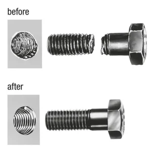
Why Use Threaded Inserts in Fiberglass Instead of Screws Alone?
I. Material Properties of Fiberglass Fiber
As a typical thermosetting composite material, glass fiber (Fiberglass) is widely used in aviation, shipping, automotive, electronics, building materials and other fields. However, its characteristics in the field of mechanical fastening and metal materials are significantly different, improper use can easily lead to structural damage or connection failure. The main performance is:
High brittleness, weak impact resistance
Although the glass fiber has good tensile strength (such as typical GFRP tensile strength up to 250-500 MPa), but its shear, impact resistance is poor. Especially in the direct action of the screw parts, when the point of force concentration, easy to trigger matrix cracking, localized peeling or delamination phenomenon, resulting in structural fatigue or even scrap.
Lack of durable thread holding power
Unlike metal, the fiberglass material itself cannot be processed to produce strong and reliable internal threads. Even when self-tapping screws are used, the initial connection firmness is limited Long-term vibration or thermal expansion and contraction, the threads are prone to slipping and loosening, and the strength of the connection decreases rapidly. In critical applications, this problem will seriously affect the stability and safety of the structure.
Sensitive to stress concentration, which can easily lead to failure
During the installation of common screws, especially during the tightening stage, the head of the screw and the threaded section will form an obvious stress concentration area. If the insert is not used for transition, it is easy to produce micro-cracks or stress spikes in the fiberglass matrix, which in turn triggers irreversible damage such as crack expansion and localized chipping.
II. Risks of direct screwing
Threads are easily damaged and have a limited number of reuses
The fiberglass substrate lacks the elasticity and toughness of metal and cannot effectively form durable internal threads. Even with the use of special self-tapping screws, its threads are also very easy to 2-3 times after disassembly and loss of bite, “idle” or fall off phenomenon.
Screws are easy to loosen, unreliable connection
In the absence of threaded inserts, the screws act directly on the fiberglass hole wall, long time vibration, thermal expansion and contraction or load changes, the hole diameter may expand, resulting in connection loosening or even completely fall off, especially in the equipment or structure in motion is more obvious.
Increased risk of localized cracking and structural failure
Tightening screws creates localized stress concentrations, and glass fibers are very sensitive to such concentrated loads. During long-term use, these micro-cracks may gradually expand into apparent cracks, interlaminar peeling or structural fractures, ultimately affecting the safety and service life of the entire product or device.
III. Advantages of using threaded inserts
| Performance Indicator | Direct Screwing | Using Threaded Inserts |
|---|---|---|
| Pull-out Strength | Low | Increased by 50%–200% (depending on insert design) |
| Number of Repeated Installations | 2–3 times | Over 10 times, some up to 50 times |
| Risk of Material Damage | High | Significantly reduced |
| Long-term Connection Stability | Poor | Good |
| Suitable Applications | Light load scenarios | Medium to heavy load, high-frequency assembly |
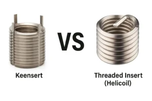
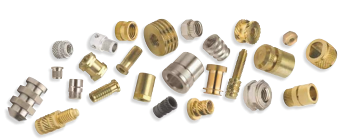
What Are Common Types of Threaded Inserts Suitable for Fiberglass?
1. Mold-in Inserts
Application method: Pre-embedded in the material during glass fiber molding (such as compression molding, injection molding).
Advantages:
- The inserts are firmly bonded to the base material, providing high structural strength;
- Formed in a single process during molding, suitable for mass production;
- Superior tensile and torsional strength compared to post-installed inserts.
Notes:
- Mold design must consider insert positioning and fixation in advance;
- Requires high precision in the molding process.
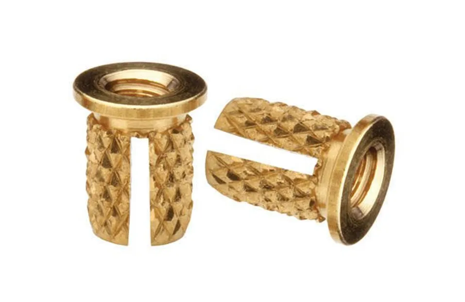
2. Press-in Inserts
Application method: Use mechanical force to press the insert into the pre-drilled hole and secure it with interference fit.
Advantages:
- Easy to install, no special tools required;
- Suitable for thick fiberglass parts;
- Some have knurled or serrated designs to enhance grip.
Notes:
- The size of the base hole must be precisely controlled;
- Excessive installation force may cause cracks or delamination in the fiberglass.
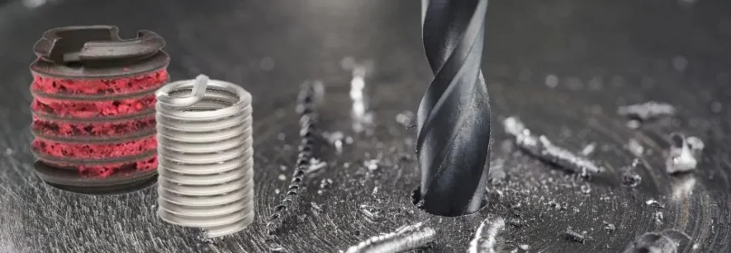
3. Self-tapping Inserts
Application Method: The inserts have self-tapping threads and can be directly screwed into pre-drilled holes without the need for tapping.
Advantages:
- Quick installation, suitable for on-site assembly or maintenance;
- Can be used in thick-walled glass fiber components;
- Strong grip force and good pull-out resistance.
Notes:
- Avoid heat buildup during installation;
- Frequent disassembly is not recommended to prevent creep or cracking of the base material.
4. Heat-set and Ultrasonic Inserts
Application method: The inserts are embedded into the base material and cured using heat pressing or ultrasonic waves.
Advantages:
- Secure installation with controllable embedment depth;
- Ultrasonic method suitable for thermosetting fiberglass composites;
- Commonly used in applications requiring high precision and repeatability.
Considerations:
- Dependent on thermal control or ultrasonic equipment;
- Not suitable for thin-walled or overly fragile components.
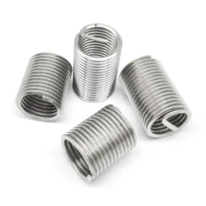
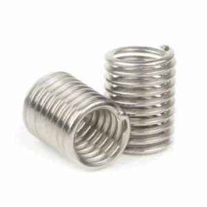
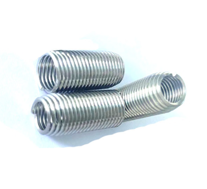
Application Method: Installed in threaded holes to form standard internal threads, similar to a spring structure.
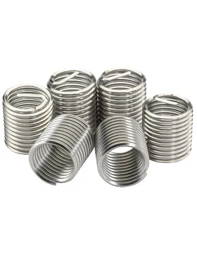
Advantages:
- Excellent vibration resistance and wear resistance;
- Can be used for thread repair or to extend thread life;
- Avoids direct stress on the base material, effectively distributing loads.
Notes:
- Installation tools must be compatible;
- For fiberglass components, special attention should be paid to the thread quality of the hole before installation.
Summary Recommendations
| Type | Installation Method | Advantages | Recommended Applications |
|---|---|---|---|
| Molded-in Inserts | Embedded during molding | Strong bond, high strength | Mass production, structural part fastening |
| Press-in Inserts | Cold press fit | Simple and quick, strong interference fit | Medium-thick wall structures, component fixing |
| Self-tapping Inserts | Threaded in | Fast installation, easy maintenance | Field repairs, on-site installation |
| Heat/Ultrasonic Inserts | Heat press / Ultrasonic | High precision, stable installation | Precision assembly, electronic components |
| Wire Threaded Inserts | Inserted into tapped holes | Wear-resistant, vibration-resistant, thread repair | Frequent assembly/disassembly, thread repair |
What Are the Key Factors When Choosing Threaded Inserts for Fiberglass?
1. Insert Material Compatibility
1.1. Chemical Stability and Corrosion Resistance
Since fiberglass products are often exposed to humid, hot, acidic, alkaline, or salt spray environments, unsuitable insert materials are prone to corrosion or material peeling:
| Insert Material | Corrosion Resistance | Recommended Environment |
|---|---|---|
| Stainless Steel 304/316 | Excellent, 316 suitable for highly corrosive environments | Outdoor, marine, chemical medium environments |
| Nickel-Plated Brass | Good, suitable for neutral/weak alkaline environments | Indoor, electrical enclosures, lightweight structural components |
| Aluminum | Poor, susceptible to alkaline corrosion, requires anodizing | Indoor, light-duty applications, non-corrosive environments |
| Carbon Steel (Galvanized/Nickel-Plated) | Low cost, prone to corrosion | Disposable applications or internal dry structures |
Recommendation: For fiberglass with alkaline corrosion potential, prioritize 316 stainless steel or nickel-plated brass to avoid long-term contact corrosion.
1.2. Galvanic Corrosion Risk
Fiberglass itself is an insulating material, but when inserts connect to conductive components (such as copper wires, stainless steel bolts), significant material differences between inserts may create a weak galvanic corrosion environment:
- Stainless steel and copper component connections: Safe;
- Carbon steel inserts connected to copper wires/copper terminals: Corrosion risk exists;
- Recommend maintaining a connection metal potential difference <0.25 V (based on the electrochemical potential series);
1.3. Thermal Expansion Coefficient Matching
The thermal expansion coefficient of fiberglass composites is 5–10×10⁻⁶/°C (smaller along the fiber direction), while that of metal inserts is typically 10–20×10⁻⁶/°C. If the thermal expansion difference is too large, long-term thermal cycling will cause the insert to loosen or the base material to crack:
| Material | Thermal Expansion Coefficient (×10⁻⁶/°C) |
|---|---|
| Glass Fiber Reinforced Plastic | 5–10 (significant directionality) |
| Stainless Steel 304 | 17.3 |
| Aluminum | 23.1 |
| Brass | 18–20 |
Recommendation: For applications with significant temperature fluctuations (e.g., engine compartments, motor housings), select materials with thermal expansion coefficients that are well-matched to GFRP (e.g., stainless steel is preferable to aluminum).
1.4. Mechanical Property Matching
- Inserts with excessively high hardness (e.g., tool steel) may crush the glass fiber during installation;
- Materials with too low hardness (e.g., soft brass) are prone to thread wear due to repeated disassembly and assembly;
- Materials within the Rockwell hardness HRB 70–100 range are generally recommended for glass fiber panel assembly.
1.5. Material Process Compatibility
- Hot-melt inserts require materials with good thermal conductivity (e.g., brass, copper alloys) ;
- Ultrasonic inserts require good plasticity and resonance response;
- Materials unsuitable for thermal processing (e.g., high-hardness steel) are not recommended for melt-in installation.
Conclusions and Selection Recommendations
When selecting insert materials for fiberglass products, the following priorities should be considered in order:
- Long-term corrosion resistance > Thermal expansion matching > Installation method adaptability > Cost considerations
- Recommended materials:
- High performance: 316L stainless steel
- General cost-effectiveness: Nickel-plated brass
- Non-critical components or low corrosion resistance requirements: Aluminum (anodized) or carbon steel (nickel-plated)
2. Pull-out Strength Requirements
Pull-out strength is a critical indicator of whether an insert can reliably withstand axial tensile forces, directly determining the safety and service life of the connection during use. This is particularly crucial in materials like glass fiber reinforced plastic (GFRP), which are highly rigid but brittle.
2.1. Definition and Calculation Standards
Pull-out strength refers to the maximum load capacity at which an insert is pulled out of the base material under vertical tensile force, typically measured in Newtons (N) or pounds-force (lbf).
Test Standard References:
- ASTM D7332/D7332M: Used for pull-out testing of metal inserts in composite materials;
- ISO 12214-3: Mechanical testing of threaded inserts in thermosetting materials;
- Companies typically use fixtures for static pull-out tests, with results used as conservative design values.
2.2. Key Factors Affecting Pull-Out Performance
| Factor Category | Impact Description |
|---|---|
| Insert Type | In-mold inserts, hot-melt inserts generally have higher pull-out strength > self-tapping > press-fit |
| Embedding Depth | The deeper the insert, the larger the contact area, and the tensile strength increases proportionally (recommended embedding depth ≥ 60% of the plate thickness) |
| Surface Structure | Knurled, spiral grooves, or barbed designs effectively enhance bite force and pull-out resistance |
| Base Material Density | High-density glass-fiber-reinforced resin exhibits superior pull-out resistance compared to low-density epoxy/phenolic base materials |
| Installation Quality | The interference fit precision between pre-drilled hole diameter and insert directly impacts pull-out resistance; loose fits significantly reduce strength |
2.3. Typical Tensile Strength Reference Values for Inserts
| Insert Type | Embedding Depth | Panel Thickness | Tensile Strength (Static) |
|---|---|---|---|
| Self-tapping insert M5 | ≥8mm | 10mm | 1,200–1,800 N |
| Hot-melt insert M6 | ≥10mm | 12mm | 2,500–4,000 N |
| In-mold insert M8 | ≥12mm | ≥14mm | >5,000 N (high-performance GFRP) |
| Press-fit insert M5 | ≥8mm | ≥10mm | 1,000–1,500 N (depending on material) |
3. Installation Method
3.1. Mold-in Installation
During the compression molding or injection molding process of fiberglass products, inserts are pre-placed in the mold so that they are molded together with the composite material.
Features:
- The insert forms a complete bond with the base material, offering the strongest pull-out/torsion resistance;
- No post-processing is required for installation, making it suitable for mass production;
- No additional processes are needed, reducing post-assembly costs.
Applications:
- Structural components, motor housings, mechanical bases;
- Mass injection molding, compression molding, RTM, and pre-preg hot pressing processes.
Notes:
- Precise positioning must be designed within the mold;
- The shape of the insert should avoid sharp angles to prevent stress concentration.
3.2. Self-Tapping Installation
Self-tapping inserts have built-in cutting threads and can be directly screwed into pre-drilled holes during installation without the need for tapping.
Features:
- Easy to operate, suitable for maintenance or on-site installation;
- Embedding depth can be controlled by torque;
- Installation does not require heat sources or vibration equipment.
Applications:
- Small to medium-volume assembly, field maintenance, electrical installation panels;
- Optimal performance when used with fiberglass panels ≥6 mm thick.
Notes:
- Pre-drilled holes must have high precision, with a diameter generally 90–95% of the insert’s minimum outer diameter;
- Installing too quickly may cause heat buildup or cracking.
3.3. Heat-Set Installation
By heating the insert (typically using an electric heating head), it is melted into the thermosetting or thermoplastic fiberglass substrate and cured to form a solid shape.
Features:
- The insert forms a local mechanical interlock with the base material;
- Commonly used for brass or aluminum inserts;
- Heat conduction must be uniform to prevent carbonization or resin erosion.
Applications:
- Electronic enclosures, thin-walled components, plastic + fiberglass composite parts;
- Thermoplastic substrates are more suitable than thermosetting ones.
Notes:
- High temperature control precision (180–220°C);
- Not suitable for materials with low thermal conductivity or excessive thinness.
3.4. Press-fit Installation
The insert is pressed into the pre-drilled hole using mechanical pressure and secured by interference fit or serrated knurling structure.
Features:
- Easy to install, suitable for medium to thick plate structures;
- Typically incorporates knurling or anti-rotation designs to enhance holding force;
- No heating or power drive required.
Applications:
- Industrial panels, instrument housings, structural connection components;
- Installation environments with temperature sensitivity or where heating is not feasible.
Notes:
- Hole diameter and interference clearance (0.05–0.15 mm) must be strictly controlled;
- Poses a stress concentration risk for thin-walled fiberglass structures; use with caution.
Installation Methods for Different Threaded Inserts
| Installation Method | Process Requirements | Installation Efficiency | Pull-out Resistance | Applicable Batch Size |
|---|---|---|---|---|
| In-mold Insertion | High (requires mold design) | ★★★ | ★★★★★ | Large batches |
| Self-tapping | Low | ★★★★ | ★★★ | Small batches/repairs |
| Hot melt | Medium | ★★★ | ★★★★ | Medium batches |
| Ultrasonic insertion | High (special equipment required) | ★★★★★ | ★★★★ | Medium to high volume |
| Press-fit | Medium | ★★★ | ★★★ | Small to medium volume |
4. Hole Size & Panel Thickness
4.1. Control Requirements for Hole Size
The core of threaded insert installation lies in the interference fit between the hole and the insert. If the hole size is too large, it may cause the insert to rotate, loosen, or even detach; if the hole diameter is too small, it may cause material expansion, cracking, or delamination during installation, particularly in brittle materials like fiberglass.
General recommendations:
- The hole diameter should be precisely machined according to the insert’s outer diameter, with a tolerance of ±0.05 mm;
- For press-fit inserts, the hole diameter should be approximately 0.1 mm smaller than the insert’s maximum outer diameter to ensure a reliable mechanical interference fit;
- For self-tapping inserts, the hole diameter should be 90–95% of the insert’s minimum outer diameter to ensure sufficient thread engagement resistance during tapping;
- For hot-melt or ultrasonic inserts, the pre-drilled hole should avoid being too tight, allowing for easy insertion without leaving noticeable gaps, ensuring uniform force distribution during the melting process;
- The hole walls must be smooth, free of burrs, delamination, carbonization, or burn marks to ensure uniform force transmission when the insert is under load.
4.2. Design Matching of Panel Thickness and Embedding Depth
Glass fiber materials exhibit significant directionality and layered brittleness in terms of mechanical strength. Panel thickness is the direct limiting factor determining the tensile and torsional performance of embedded components. If the embedding depth is insufficient, it is highly likely to cause pull-out failure; conversely, excessive depth may lead to cracking or penetration at the panel bottom.
Engineering experience suggests the following:
- When panel thickness is less than 3 mm, threaded inserts are not recommended, as the glass fiber thickness is insufficient to provide an effective anchorage zone;
- When panel thickness is 4–6 mm, only short-type inserts or ring grooves/short-thread designs are recommended, with sufficient edge spacing required;
- When panel thickness is ≥8 mm, inserts can be designed as standard or reinforced types to meet medium to high load requirements;
- Generally, the embedment depth of the insert should be ≥60% of the panel thickness, preferably 70–80%, to ensure maximum contact area and load distribution;
- For applications with high tensile strength requirements (such as structural connections or load-bearing ends), the insert length should be equal to or slightly less than 90% of the panel thickness to avoid penetrating the structure or causing cracks on the underside.
5. Environmental Factors
5.1. Corrosion Resistance
Corrosion is the primary environmental factor affecting the service life and structural reliability of inserts. Glass fiber products are commonly used in coastal areas, chemical plants, electrical enclosures, and other locations where the environment may contain moisture, salt fog, acidic or alkaline gases, and other substances that pose a continuous corrosion threat to metal inserts.
For such environments, the following materials should be prioritized:
- 316L Stainless Steel: Offers excellent resistance to chloride corrosion, particularly suitable for high salt fog, acidic gas, or humid enclosed environments;
- Nickel Alloys (e.g., Monel, Inconel): Suitable for extremely corrosive environments, such as petrochemical plants or offshore equipment;
- Nickel-plated brass: Maintains good stability in moderate humidity or weak acid/alkali environments, suitable for indoor distribution panels, electrical control cabinets, and other components;
- Corrosion-resistant coated carbon steel inserts (e.g., zinc-chromate coating, fluorocarbon coating): A secondary option in cost-sensitive environments with moderate corrosion levels.
Avoid using bare copper, uncoated carbon steel, or metal combinations with significant potential differences. These materials can accelerate corrosion, expansion, or even structural failure within fiberglass structures due to microgalvanic reactions or electrolyte intrusion.
5.2. High-Temperature Resistance
Thermal environments significantly impact the installation stability and long-term dimensional stability of inserts, particularly near heat sources such as motors, engine compartments, and electrical enclosures.
Different installation methods exhibit varying sensitivity to temperature:
- Thermoplastic inserts: These rely primarily on thermal conduction to soften and cure the resin, with an operating temperature typically not exceeding 220°C. If exposed to high temperatures or cyclic thermal cycling (e.g., >200°C) over extended periods, the base material may experience stress relaxation, leading to gradual loosening or failure of the insert.
- Ultrasonic inserts: Structural locking relies on microscopic mechanical bonding formed by vibrational impact, offering relatively better temperature resistance, typically capable of withstanding operating temperatures around 250°C.
- In-mold inserts and self-tapping inserts: Thermal stability depends on the degree of mechanical interlocking with the base material. If the base material has good thermal stability, the structure is relatively reliable.
In high-temperature environments, it is recommended to prioritize the use of heat-resistant metals (such as 316 stainless steel or titanium alloys) for inserts, combined with resin substrates with high Tg (glass transition temperature), such as phenolic resin or high-performance epoxy resin, to ensure long-term dimensional stability.
5.3. Vibration and Impact Resistance
For structures subjected to vibration or periodic impact loads (such as vehicle frames, power tool housings, wind power equipment, etc.), inserts must not only have sufficient static strength but also excellent anti-loosening and anti-rotation capabilities to prevent gradual loosening under micro-motion fatigue.
The following structural designs can enhance dynamic stability:
- Select inserts with locking grooves or external knurled structures;
- Use anti-rotation geometric shapes such as hex heads, chamfered edges, or barbed edges;
- Apply anti-loosening structures (e.g., nylon locking nuts, stop washers) to the screws mating with the inserts;
- Use appropriate force control during installation to avoid over-tightening that could damage the boundary integrity of the fiberglass material.
Summary: Choosing the Right Threaded Insert for Fiberglass Projects
When selecting the appropriate threaded insert for a fiberglass project, it is essential to accurately match the structural performance requirements with the operating environment conditions. First, determine whether the project involves high loads or frequent disassembly and reassembly. If so, prioritize inserts with high tensile strength and reliable installation, such as in-mold inserts or hot-melt inserts. For maintenance or small-batch on-site assembly, self-tapping inserts offer greater efficiency and flexibility.
Second, panel thickness determines the insert length and anchoring method. Generally, the panel thickness should be no less than 3 mm, and the insert length is recommended to be ≥ 60% of the panel thickness. Additionally, environmental conditions must be fully considered. For example, in corrosive environments, 316 stainless steel or nickel alloy inserts should be selected, while in high-temperature areas, hot-melt methods should be avoided, and ultrasonic or in-mold inserts should be used instead.
Do You Have Any Questions?
Let Us Solve Your Problem
Choose the Right Inserts for Stronger Fiberglass Connections
Whether it’s mass-produced composite components or durable outdoor structural parts, choosing the right threaded inserts can significantly enhance connection strength and long-term stability. Rivetfix offers high-strength threaded inserts specifically designed for fiberglass, including brass press-in, self-tapping, and stainless steel wire inserts, providing versatile solutions for various installation requirements and environmental challenges.
Custom Rivetfix’s Threaded Inserts today to make your fiberglass projects more secure and professional!
Get High Quality Rivet Nuts Quote!

Send Your Rivet Nut Request
For more than 20 years, Rivetfix has helped customers solve many rivet nuts sourcing needs and technical challenges.
Have a question? Contact us and we’ll provide you with the perfect solution.