What Keeps a Rivnut from Spinning?
Leading Rivet Nut Manufacturer and Supplier in China
When installing a Rivnut (rivet nut), one of the most critical challenges engineers face is preventing it from spinning inside the base material during or after installation. A spinning Rivnut can lead to failed joints, reduced load capacity, and costly rework. So, what keeps a rivnut from spinning? In this blog, we’ll explore the key design features, installation practices, and material considerations that ensure a secure, rotation-resistant Rivnut connection—even under high torque or vibration.
Table of Contents
Why Rivnut Spin-Out Matters?
“Spin-out” refers to the situation where a rivnut begins to rotate inside the base material during bolt tightening or usage. This failure mode can severely compromise the stability and reliability of the entire fastening system, with the following consequences:
1. Inability to Apply Proper Torque
A rivnut serves as the internal thread support for a bolt and must be securely anchored in the base material. If it spins:
- The bolt cannot be properly torqued because the rivnut rotates with it;
- No clamping force is generated, leading to a loose joint;
- The assembly fails, which is especially problematic on automated production lines.
2. Installation Failure and Material Waste
When a rivnut spins during or after installation, it typically cannot be reused without repair or rework. This leads to:
- High rework costs: The failed rivnut must be removed and the hole re-prepared or enlarged;
- Material damage: Thin or soft materials like plastics may be permanently damaged, resulting in scrapped parts;
- Low efficiency: Frequent spin-out issues can significantly slow down production or field assembly.
3. Risk to Structural Integrity
In applications with vibration, impact, or shear loads, a spinning rivnut means the joint loses mechanical reliability, which may cause serious consequences:
- In automotive, aerospace, and rail applications, a single failed rivnut could result in part detachment;
- In load-bearing structures, spin-out prevents proper load transfer and introduces safety risks;
- Under dynamic stress, spin-out accelerates fatigue in surrounding materials, shortening service life.
What Prevents a Rivnut from Spinning?
In practical use, if a Rivnut spins during tightening or under load, it will cause connection failure and prevent the bolt from properly locking. To avoid this issue, Rivnuts have clear anti-rotation mechanisms built into their structural design and installation process. Below is a detailed analysis of how Rivnuts prevent spinning from three aspects:
a. Structural Design
The body shape of the Rivnut is the core factor for its anti-rotation performance. It improves resistance to rotation through “mechanical interlock” or “surface friction” between the Rivnut’s shape and the hole in the base material.
- Hex Body: Suitable for metal plates or profiles pre-punched with hexagonal holes. After installation, the outer edges of the Rivnut fit tightly with the hole walls, achieving mechanical locking. This is the strongest anti-rotation design.
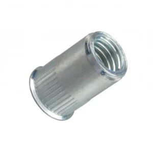
- Knurled Body: The surface of this Rivnut has longitudinal knurls or serrations, which, when expanded into a round hole during installation, create strong friction with the hole wall to enhance anti-rotation.
- Hex / With Anti-Rotation Slot: Combining hex and round shapes, this design is suitable for holes with positioning slots or stamped parts. It improves adaptability to hole variations and enhances anti-rotation effect.
b. Proper Hole Preparation
Whether a Rivnut can resist spinning also highly depends on the hole size and shape matching.
- Oversized Holes: Cause the Rivnut to be loose inside the hole, making mechanical interlock ineffective even if the Rivnut structure is good.
- Mismatched Hole Shape: For example, installing a hex Rivnut into a round hole completely loses its anti-rotation ability.
- Recommended Tolerance: Usually, the installation hole tolerance is ±0.05 mm (depending on the Rivnut model). Excessive hole size deviation seriously affects anti-rotation performance.
| Rivnut Type | Recommended Hole Shape | Recommended Hole Diameter (mm) | Tolerance (mm) | Notes |
| Hex Body | Hexagonal | Exact to Rivnut body size | ±0.05 | Ensures mechanical interlock |
| Knurled / Serrated | Circular | Rivnut outer diameter – 0.02 to 0 mm | ±0.05 | Allows strong friction fit |
| Semi-Hex / Anti-Rotation Slot | Hex with slot or oval | Match slot dimensions +0.01 to +0.03 | ±0.05 | For stamped parts or locating slots |
| Round Smooth Body | Circular | Rivnut outer diameter +0.01 to +0.05 | ±0.05 | Usually used with adhesives or welding |
c. Riveting and Forming Pressure
The anti-rotation performance of a Rivnut depends not only on its body design and hole preparation, but also critically on whether the installation pressure (or pulling force) applied during riveting is sufficient. Inadequate force can lead to poor deformation and insufficient clamping, resulting in spin-out or loosening.
1. Function of Installation Pressure
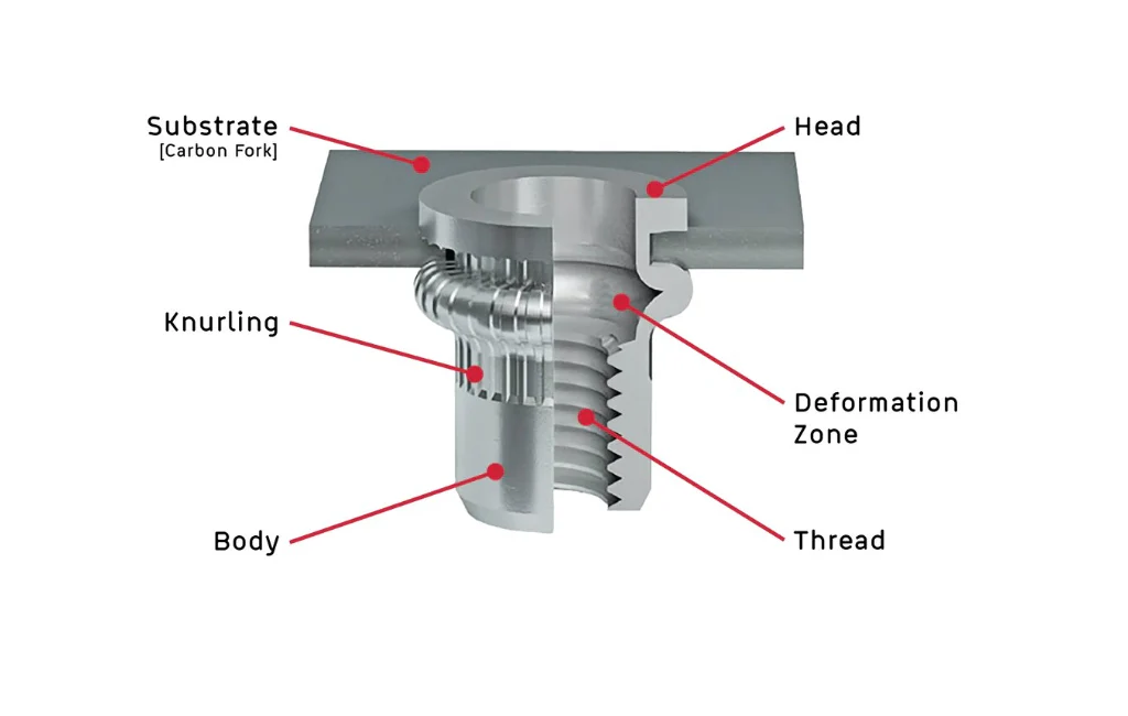
The Rivnut installation process involves applying axial pulling force using a special tool. This force causes the tail end of the nut to plastically deform and flare out behind the base material, forming a “blind-side flange” that tightly clamps the Rivnut in place. If the pressure is too low, the Rivnut will not fully deform or clamp tightly, reducing friction and increasing the risk of spinning or loosening.
2. Recommended Pulling Force Values
Different materials and thread sizes of Rivnuts require different levels of installation force. Typical reference values are as follows (actual requirements may vary by manufacturer):
| Rivnut Material | Thread Size | Recommended Pulling Force (kN) |
| Aluminum Alloy | M6 | 5.5 – 7.0 |
| Carbon Steel | M6 | 8.0 – 10.0 |
| Stainless Steel | M6 | 10.0 – 13.0 |
| Aluminum Alloy | M8 | 7.0 – 9.0 |
| Carbon Steel | M8 | 10.0 – 12.0 |
| Stainless Steel | M8 | 13.0 – 16.0 |
Note: Too little force leads to incomplete deformation; excessive force may damage the base material or break the Rivnut.
3. Installation Tool Setup Recommendations
- Hydraulic or pneumatic Rivnut tools should be set with proper pulling force and stroke length.
- The setup must ensure full expansion of the tail without damaging the surface or excessively flattening the Rivnut.
- Tools with force/stroke control features are recommended for high-precision and adjustable installations.
4. Relationship Between Material and Clamping Force
After proper installation, the Rivnut’s clamping force against the base material can reach 3–10 kN (depending on the Rivnut size, material, and installation quality). If the clamping force is insufficient, spin-out or pull-out may occur, especially in soft base materials like plastic, fiberglass, or thin aluminum sheets. In such cases, it is recommended to use knurled or serrated body Rivnuts and apply higher pressure to enhance anti-rotation performance.
How Can You Ensure Rivnut Installation Prevents Spinning?
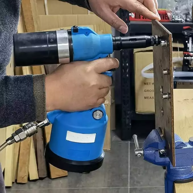
1. Use Specialized Installation Tools
Ensure the use of dedicated rivet nut installation tools that provide stable and controllable pulling force and stroke:
- Manual Rivet Nut Gun: Suitable for small quantities or maintenance work; easy to operate but requires manual control of force;
- Pneumatic Rivet Nut Gun: Suitable for medium-volume production; fast and consistent, commonly used for aluminum or small-size rivet nuts;
- Hydraulic Rivet Nut Gun: Suitable for large-size or stainless steel rivet nuts; provides stronger pulling force, recommended for structural connections or thick materials.
It is advised to select equipment with a pulling force range matched to the thread size and substrate strength, and to regularly calibrate the tool’s pulling force to ensure it remains within the qualified range. The required force depends not only on the Rivnut’s thread size (e.g., M5, M6, M8) but also on its material (such as aluminum, carbon steel, stainless steel) and the hardness and thickness of the base material.
Taking the common M6 thread size as an example:
- For aluminum rivet nuts, a pulling force of about 5.5–7.0 kN is usually sufficient for proper setting;
- For carbon steel rivet nuts, the recommended pulling force range increases to about 8.0–10.0 kN;
- For stainless steel rivet nuts, due to their higher yield strength, at least 10.0–13.0 kN of pulling force is required to ensure full expansion of the rivet tail.
Taking the M8 stainless steel rivet nut as an example:
The forming pulling force can reach 14–16 kN. Using an ordinary pneumatic tool at this point may lead to incomplete setting, insufficient tail expansion, or rivnut spinning, seriously compromising structural safety.
Key considerations when selecting tools include:
- The tool’s rated pulling force should exceed the Rivnut’s required forming force by 10%–20%, providing sufficient margin for variations in substrate hardness or assembly tolerances;
- For aluminum or thin-walled rivet nuts below M6 size, pneumatic tools with a pulling force range of 6–9 kN are suitable;
- For carbon steel or stainless steel rivet nuts of M6/M8 size, hydraulic tools with a pulling force range of 12–18 kN should be used;
- If the base material is hard steel or thick plate, the pulling force should be further increased to ensure full tail expansion;
- Some advanced hydraulic tools support “stroke adjustment + pulling force feedback” functions, allowing automatic control of the setting process based on actual deformation of the rivet nut tail, ideal for precision or structural connections.
Additionally, it is recommended to perform pulling force calibration tests using a pull gauge or test bolt before large-scale installation to ensure the tool’s output remains stable and avoid anti-rotation failure caused by installation variability.
2. Inspect the Base Material Hole Quality
Improper hole preparation significantly affects anti-rotation performance. Before installation, the following checks should be performed:
- Remove Burrs: Burrs on the hole edges can prevent the rivet nut from fully mating with the hole wall, creating micro-gaps that lead to spinning;
- Clean the Hole Interior: Oil, metal shavings, dust, or other contaminants inside the hole reduce friction and adversely affect clamping force;
- Confirm Hole Diameter Tolerance: The hole diameter tolerance is usually controlled within ±0.05 mm. The exact value should be referenced from the installation manual for the specific rivet nut model. Using CNC machining, precision punching, or laser cutting to achieve high accuracy ensures the hole diameter matches the rivet nut outer diameter precisely, thereby maximizing anti-rotation performance.
3. Structural Optimization for Soft Materials
When the base material is low-strength or soft materials such as plastic, fiberglass, wood, or thin aluminum sheets, consider the following optimizations:
- Use Large Flange Rivnuts: Increase the contact area with the base material surface to distribute load and improve anti-rotation force;
- Choose Open-End Structures: Helps form a stronger flange clamp, suitable for low hardness materials;
- Use Knurled or Serrated Body Types: Enhance mechanical engagement with the hole wall and improve anti-rotation performance.
4. Add Reinforcement Plates Behind the Riveting Area
Adding reinforcement structures behind the base material significantly improves installation stability and resistance to spinning:
- Install Metal Reinforcement Washers or Sandwich Plates: Provide additional support for thin or low-rigidity base materials;
- Suitable for Composite or Sandwich Panels: Such as honeycomb aluminum panels, plastic foam sandwich panels, etc. Reinforcements effectively prevent rivet nut pull-out or spinning;
- Pre-installed Insert Plates: In high-end applications, metal seats or nut plates can be embedded inside the hole before installing the rivet nut.
Summary Recommendations:
To minimize rivet nut spinning, engineers should perform the following pre-installation checklist:
- Verify the installation tool matches the required pulling force specification and has been calibrated;
- Ensure the base material hole is clean, burr-free, and meets the recommended diameter tolerance;
- Confirm the rivet nut structure matches the material hardness (e.g., large flange, knurled type);
- Check whether reinforcement plates or inserts are present behind the riveting area;
- Conduct installation trials to confirm full rivet tail deformation.
Do You Have Any Questions?
Let Us Solve Your Problem
How Do Material and Application Factors Affect Rivnut Anti-Rotation Performance?
The anti-rotation performance of Rivnuts is significantly affected by the base material. To ensure installation stability, it is important to select the appropriate Rivnut type and structural design according to different substrates:
Steel and Aluminum Plates:
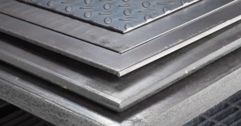
These metal materials have higher hardness and good mechanical strength. It is generally recommended to use hexagonal Rivnuts installed in hexagonal holes. Hexagonal Rivnuts achieve the best anti-rotation effect through mechanical locking, effectively resisting high torque and loads. They are suitable for structural components and load-bearing parts.
Plastic and Composite Materials:
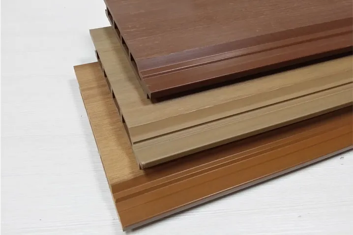
Plastics, fiberglass-reinforced plastics (FRP), and other composites usually have lower hardness and are prone to material deformation and hole looseness. Using standard hexagonal Rivnuts directly may cause spinning or slipping. In these cases, it is recommended to use large flange Rivnuts to increase the contact area and distribute the load, combined with embedded structural designs.
Applications with Frequent Vibration or Dynamic Loads:
In environments with frequent vibrations or dynamic loads, relying solely on the Rivnut’s anti-rotation design may not guarantee long-term secure connections. In such cases, it is advisable to use locking hardware with the bolts, such as locking washers (spring washers, nylon lock washers, etc.), to prevent loosening and improve the overall vibration resistance and safety.
Additionally, environmental factors such as temperature variations, humidity, and corrosion should be considered. Selecting Rivnuts with appropriate corrosion resistance and coatings ensures long-term anti-rotation reliability and structural safety.
What Causes Common Rivnut Spin-Out Failures and How Can They Be Troubleshooted?
Rivnut spin-out issues not only affect joint strength but can also lead to equipment failure and safety risks. Based on root causes and practical engineering experience, the following detailed troubleshooting and solutions are provided.
① Improper Hole Size or Incorrect Hole Shape
Failure Mechanism:
Rivnuts rely on mechanical locking or friction with the hole wall to prevent spinning. If the hole diameter exceeds tolerance or the hole shape does not match the Rivnut, mechanical locking cannot be achieved, causing spin-out.
Detailed Troubleshooting Steps:
- Use high-precision calipers, bore gauges, or pin gauges to measure the hole diameter, confirming it is within the manufacturer’s recommended installation tolerance (usually ±0.03~0.05 mm). Large tolerance deviations require process adjustments.
- Check if the hole shape matches the Rivnut type—for example, hexagonal Rivnuts must be installed in hexagonal holes; otherwise, anti-rotation effect will be greatly reduced.
- Inspect if the hole wall is smooth and perpendicular. Non-perpendicular or burr-ridden holes cause uneven contact, weakening the mechanical lock.
- Sample and measure holes on-site to verify process stability; provide feedback to the manufacturing department if deviations exist.
Recommended Solutions:
- Use higher-precision CNC punching, laser cutting, or stamping equipment to produce holes.
- Add chamfers to the hole edges if necessary to improve Rivnut fit.
②. Insufficient or Uneven Riveting Pressure
Failure Mechanism:
Insufficient pulling force during installation causes the Rivnut tail to fail to fully expand and form a secure “flange,” resulting in increased gap between Rivnut and base material, lowering clamping and anti-rotation performance.
Detailed Troubleshooting Steps:
- Use a pull force gauge to check the actual pulling force of the riveting tool, ensuring it meets requirements, especially in mass production with regular calibration.
- Check the installation stroke settings; too short or too long stroke can affect forming quality. Ensure it complies with the Rivnut manufacturer’s recommended parameters.
- Inspect the deformation of the installed Rivnut tail; it should be uniform, full, without cracks or obvious defects.
- Check the maintenance condition of the riveting tool; worn or damaged tools reduce pulling force and stability.
Recommended Solutions:
- Select equipment with rated pull force 10%-20% higher than the Rivnut’s forming force requirement to ensure margin.
- Use matched installation tools (manual, pneumatic, hydraulic) for different Rivnut sizes and materials to ensure stable pulling force.
- Regularly maintain and calibrate installation equipment to maintain precision.
③. Burrs, Contamination, or Uneven Hole Walls in Base Material
Failure Mechanism:
Burrs and contaminants create tiny gaps between the hole wall and Rivnut contact surface, reducing friction and clamping force, leading to spin-out.
Detailed Troubleshooting Steps:
- Visually inspect holes under magnification for burrs or flash.
- Use chamfering tools to remove burrs and avoid sharp edges or irregular surfaces.
- Check for oil, metal shavings, dust, and thoroughly clean holes with appropriate cleaning agents and compressed air.
- Inspect hole walls for smoothness, ensuring no significant bumps or cracks.
Recommended Solutions:
- Standardize processes to ensure chamfering and cleaning after hole processing.
- Add cleaning steps in the production line to keep holes clean.
- Consider surface treatments like shot peening on the hole walls to increase friction.
④. Insufficient Hardness or Material Mismatch of Base Material
Failure Mechanism:
Soft materials such as plastics, thin aluminum, or composites have low strength, causing local deformation around the Rivnut after installation, enlarging the hole or causing cracks, reducing anti-rotation capacity.
Detailed Troubleshooting Steps:
- Confirm base material type and hardness using hardness testers or material specs.
- Observe for deformation, cracks, or looseness around installed Rivnuts.
- Verify if material thickness meets the minimum installation requirements of the Rivnut.
Recommended Solutions:
- Use Rivnuts with large flange, knurled, or serrated designs to improve mechanical locking.
- Add metal or composite backing plates behind the base material to increase rigidity.
- Employ insert installation methods by embedding metal sleeves or nut seats in the base material to increase installation strength.
⑤. Effects of Vibration, Impact, and Dynamic Loads
Failure Mechanism:
High-frequency vibration and impacts reduce friction between the bolt and Rivnut, gradually loosening the connection and eventually causing Rivnut rotation failure.
Detailed Troubleshooting Steps:
- Check if bolts use anti-loosening washers, locking adhesives, or other locking devices.
- Evaluate vibration frequency and amplitude in the actual operating environment.
- Monitor for thread wear or looseness in the connection area.
Recommended Solutions:
- Use spring washers, nylon locking washers, or thread locking adhesives to assist fastening.
- Reinforce connection structures to reduce vibration transmission.
- Use Rivnuts with locking features or mechanical locking methods for critical equipment.
Overall Troubleshooting Recommendations
When encountering Rivnut spin-out issues, engineers should perform systematic troubleshooting across four dimensions: design, processing, installation, and operational environment:
- Design: Select Rivnut types and sizes compatible with the base material and working conditions;
- Processing: Strictly control installation hole size tolerance and surface quality;
- Installation: Ensure riveting tool pull force is adequate and parameters are correct; installation procedures must be standardized;
- Environment: Consider vibration, impact, and other dynamic factors; use appropriate anti-loosening measures.
Conclusion: What Keeps a Rivnut from Spinning?
Achieving a reliable Rivnut installation starts with well-thought-out engineering design. This includes selecting the appropriate thread size, body style (such as hexagonal, knurled, or large flange), and ensuring compatibility with the material type and thickness. A properly designed configuration not only enhances anti-rotation performance but also prevents potential failures that could lead to rework or structural safety issues.
Good design should also account for the entire installation process, including recommended hole tolerances, suitable tool force output, and a consistent assembly sequence. This ensures installation is repeatable, stable, and efficient in real-world applications.
In short, a successful Rivnut application begins at the design stage with a clear focus on anti-spin, anti-loosening, and firm clamping. Only through the coordinated optimization of design, manufacturing, and installation can the Rivnut maintain secure, long-lasting performance without spinning or loosening over time.
Do You Have Any Questions?
Let Us Solve Your Problem
Buy Rivet Nuts from Rivetfix

As a leading fastener manufacturer in China with more than 15 years in the industry, Rivetfix are committed to providing first-class quality fasteners and responsive services to the world. We offers a wide range of rivet nuts and clinch nuts designed to meet the unique demands of your projects. Rivetfix ensures you have the right solution for every application. Choose Rivetfix for versatile, cost-effective, and durable fastening solutions tailored to your specific needs. In addition, we can also provide customized rivet nuts service and clinch nuts according to your requirements.
Contact us now for more information and customization options on Rivet Nuts!
Get High Quality Rivet Nuts Quote!

Send Your Rivet Nut Request
For more than 20 years, Rivetfix has helped customers solve many rivet nuts sourcing needs and technical challenges.
Have a question? Contact us and we’ll provide you with the perfect solution.